
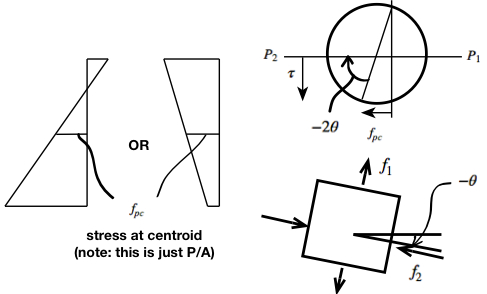
Recall from ‘Mechanics of Elastic Materials’:
(1) 
Using our notation in the above diagrams, with all quantities taken as positive:
(2) 
(3) 
As the axial compressive stress increases, the shear stress required to cause cracking will increase and the inclination of the cracks to the longitudinal axis will decrease.
Initial web-shear cracking for prestressed members:

where  is the vertical component of the PT

 is essentially
  , and adding
  captures the idea that a greater PT force increases shear capacity.
Initial flexure-shear cracking for prestressed members:

 , here, since we’re assuming uncracked behavior
Note:  is NOT constant along the length of the beam, except for beams with tendons of constant eccentricity.
 , else use
  in the above equations
e.x. – estimating diagonal cracking shears – stirrups considered effectively absent
Web-shear cracking:

where 


We now need to determine the uniform load w that causes a shear of  at a location of
  from midspan.
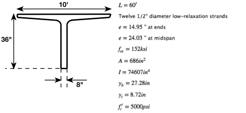
Note: The beam can be assumed to rest on a bearing pad of 8”.
50 strand diameters is  . The distance of 50 strand diameters is typically taken from the far end of the beam, while the distance at which BMDs and SFDs typically start, assumes the origin to be at the center of the support i.e. the center of the bearing pad, rather than the far end of the beam. Thus,
  , or
, or  , which is the distance from the center of the support, which is the distance of most interest to us.
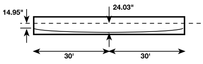
This is how we obtained the value of from midspan for the following calculations.
Now, imagine looking at a FBD of the middle  :
:
(4) 
Flexure-shear cracking:


The moment-to-shear ratio at a distance of x =  from the center of the bearing pad:
(5) 


where  ,
,  , and
, and 
The load w, required to cause this shear is:

We can repeat the above calculations for a number of different locations along the length of the beam, and tabulate.
Typically, (1) controls near the support and (2) controls away from the support, though not necessarily at midspan, since increases towards midspan for draped or harped tendons.
The previous procedure for calculating  (
( and
and  ) must be used if the effective prestress force is less than 40% of the tensile strength of the tendons. Typically, we are above 40%, in which case the following single formula for can be used:
(6) 
The following procedure will assume that the effective prestress force is greater than 40% of the tensile strength of the tendons.
Typical Shear Design: Step-By-Step
Section dimensions assumed to have been calculated based on other criteria. Loads known.
 Choose stirrup size – if #3, then
Choose a distance x along the beam. Calculate  and
and  at our distance x.
We can start with the location of maximum shear force .
Calculate from 
( was the upper limit for RC design)
 , the ‘simplified’ formula for in RC design, can be taken here as a lower limit.
(7) 
For pre-tensioned members, must not exceed within the transfer length.
We want to conservatively account for the lack of prestressing effectiveness (force  , and , which depends on the prestressing magnitude and location) near the supports. There is no or term in the above equation for , but those terms are present in and , hence the logic behind the aforementioned criteria involving .
If  , then solve for
  from
from 
 no stirrups needed
 solve for from
  or
or  , whichever is smaller
Calculate  and
and  .
.
If  , then check
  and
and  .
.
If  , then check
  and
and  .
.
If  , then we need to go back to the very beginning and choose a new section
  .
.
Check 
Check 
If any are violated, decrease ; take a new and repeat, starting with a new  . If more than one check is violated, use the smaller value.
Repeat the procedure for various sections along the beam. Sections with a different and .
Finding from  criteria, then finding
  , is an alternate approach;
The web steel volume is the same either way.
The former approached outline above in detail is generally used, since having many different stirrup sizes (different ), would be a hassle. The exact arrangement is always up to the design engineer. Safety and ease of construction should be taken into consideration.