
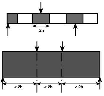
Structural members are divided into B-Regions and D-regions.
Plane sections do NOT remain plane in D-regions.
D-regions occur adjacent to point of concentrated force.
Based on St. Venant’s Principle, the normal stresses (due to axial load and bending) approach the familiar linear distribution at a distance approximately equal to the larger of the member height h or the member width, away from the location of the concentrated force.
The strut-and-tie method was introduced to facilitate the design of these D-regions.
The shaded regions, shown below, represent D-regions.
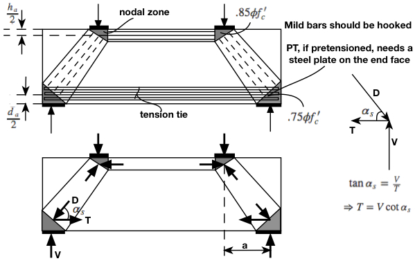
In designing a D-region, such as a deep beam, the first step is to sketch the flow of forces. At the intersection of struts and ties, or multiple struts, are nodal zones.
The nodal zones must be large enough to ensure that the nodal zone stresses remain below permissible limits.
For nodal areas bounded by struts and bearing areas, the capacity is $.85\phi f’_c$.
For nodal zones anchoring one tension tie, the capacity is $.75 \phi f’_c$
For nodal zones anchoring multiple ties (ties in multiple directions), the capacity is $.60 \phi f’_c$
These capacities will hereafter be referred to as $\phi f_{2 max}$, which is a variable that is used throughout common literature.
note: $\phi = .70$, for compression.
For analysis (applied load $V$ known, and we want to check applied stresses):
$(V_{applied})_{ST}$ generally decreases as $d_a$ decreases, despite the increasingly steep angle $\alpha_s$ .
This is because the moment arm between $C$ and $T$ increases, thus reducing the applied strut forces.
We want $(V_{applied})_{ST} = (V_{applied})_{\Sigma F_y}$ or else the system is not in equilibrium.
$D$ generally decreases as $d_a$ decreases, as well.
This is a good thing, since the nodal zone area on the tension side is constant (or at least does NOT depend on $d_a$). The downside to decreasing $d_a$ is that the nodal zone area on the compression side decreases.
So, we must choose $d_a$ such that $(V_{applied})_{ST}$ matches $(V_{applied})_{\Sigma F_y}$ (typically trial and error is the quickest method, though setting up a direct analytical solution for $d_a$ is surely possible). Then we can check stresses at the two nodal zones. Bearing plate areas, strand areas, strand spacings, can be increased if any nodal zones are overstressed. Beam width and depth increases also help.
To resist the tension force, $N_u$, due to factored loads, the area of reinforcement in the tension tie must satisfy $\phi (A_sf_y + A_{ps}f_{ps}) \geq N_u$
For $ST$ tension checks $\phi = .90$,
For compression: $\phi A_c f_{2 max} \geq N_u$
$A_c$ is the effective cross-sectional area of the strut
For $ST$ compression checks $\phi = .90$,
Where a strut is anchored by a tension tie, $f_{2 max} = \frac{f’_c}{.8 + 170 \epsilon_1} \leq .85 f’_c$
\begin{equation} \epsilon_1 = \epsilon_s + (\epsilon_s + 0.002)\cot^2(\alpha_s) \end{equation}
Reducing $\alpha_s$ results in larger values of $\epsilon_1$ and hence lower values of the crushing strength $f_{2 max}$. At the limit, no compressive stresses would be permitted in a strut that is superimposed on a tension tie ($\alpha_s = 0$).
e.x.
$h = 24”$
$d = 21.2”$
$.5 h_a= (24 – 21.2)”$
$a = 2d$
$b = 6.1”$
$f’_c=3.94ksi$
top bearing plate length = bottom bearing plate length $= 6”$
$A_s = 3.53 in^2$
Find the capacity, $V$, for this beam:
Try $d_a = 3″$
From the above deep beam diagram,
\begin{equation} \tan{\alpha_s} = \frac{h – .5h_a – .5d_a}{a} = \frac{24 – (24-21.2) – .5*3}{2*21.2} = .465\end{equation}
$\therefore \alpha_s = 24.9^\circ$
$C = T = V\cot{\alpha_s}$
The capacity of the top horizontal strut can be found simply from:
$C = 1.0 * 6.1 * 3.0 * .85 * 3.94 = 61.3 kips$
Where 1.0 is $\phi$ (assume this e.x. is for research purposes, comparing to experimental results), $6.1*3.0$ is $A_c$, $.85$ is the factor to be used for nodal zones bounded by compressive struts and bearing areas (the top nodal zones for this beam), and $3.94 ksi$ is $f’_c$.
$V = 61.3 * .465 = 28.5 kips$
Where $.465$ is $\frac{1}{\cot{\alpha_s}}$
The compressive force, $D$, in the diagonal strut:
\begin{equation} D = \frac{V}{\sin{\alpha_s}} = \frac{28.5}{\sin{24.9^\circ}} = 67.7 kips \end{equation}
The top ends of the diagonal struts are not crossed by tension ties, and hence, $f_{2max}$ at these locations can be taken equal to $.85 f’_c$.
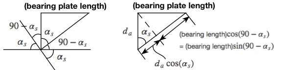
$\phi A_c f_{2 max} = 1.0 * 6.1 * (6\sin{24.9^\circ}+3\cos{24.9^\circ})*.85 * 3.94 = 107.2 kips$
where $6”$ is the top bearing plate length and $3” = d_a$
The bottom ends of the diagonal struts are crossed by a tension tie, and hence, it is necessary to determine $f_{2 max}$ , based on the strain of the tension reinforcement:
$\epsilon_s = \frac{61.3}{3.53*29000} = .60\text{x}10^{-3}$ where $61.3 kips$ is $C$, and $3.53 in^2$ is the area of the reinforcement
Half of this strain value is appropriate, in order to account for development lengths:
$ \therefore \epsilon_1 = .3\text{x}10^{-3} + (.30\text{x}10^{-3} + .002)\cot^2{24.9^\circ} = 10.97\text{x}10^{-3}$
The capacity of the nodal zones at the bottom ends of the struts:
$\phi$A_c f_{2 max} = 1.0*6.1*(6\sin{24.9^\circ} + 2*(24-21.2)\cos{24.9^\circ})*1.48 ksi = 68.7 kips \therefore \text{ OK}$
Where $6″$ is the bottom bearing plate length and $2*(24 – 21.2)”$ is $h_a$
Clearly, $C_{applied}$ should equal $T_{applied}$, simply from $\Sigma F_x = 0$. However, our above values for C and T are capacities, so we can just take the smaller value.
Using this value, we can calculate $V$, based on $\Sigma M = 0$ as follows:
$V * a = C *( h – \frac{d_a}{2} – \frac{h_a}{2})$, where $(h – \frac{d_a}{2} – \frac{h_a}{2})$ is the moment arm between $C$ and $T$.
$\Rightarrow V = 61.3*(24-(24-21.2) – .5*3)/(2*2.2) = 28.5 kips$ EXACT MATCH
Therefore, we can say that the capacity $V$ for this beam is $28.5 kips$
Note: If we did not reach an exact match for $V$, then an adjustment would have to be made in our guess for $d_a$.
Prestressing offers minimal advantage over mild reinforcing, for deep beams.
To understand why, let’s consider the following stress diagrams for a prestressed beam:
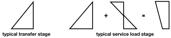 We know that deep beams do not obey this linear stress distribution, but we can consider it for illustrative purposes. The top compression fiber is subjected to the same stress, from the applied load, whether or not the member is prestressed. The difference between a mild-reinforced beam and prestressed beam is that in the case of the prestressed beam, the bottom fiber is no longer of particular concern. If the stress in the top fiber is below capacity, then the bottom fiber should also be below capacity. Thus, the design procedure for a prestressed deep beam subjected to the loading conditions of our previous example, would be unchanged, except the bottom nodal zones would NOT have to be checked.