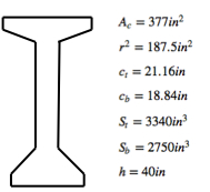
The following tables, along with the table presented in the first section of this chapter regarding sheathing eccentricity (where post-tensioning is used), are commonly used for working stress design.
Prestressing Strand and Bar Sizes
| Tendon Type | Grade |
Diameter (in) | Area (sq. in) |
|---|---|---|---|
| Seven-Wire Strand | 250 | 1/4 | 0.036 |
| 270 | 3/8 | 0.085 | |
| 250 | 3/8 | 0.08 | |
| 270 | 1/2 | 0.153 | |
| 250 | 1/2 | 0.144 | |
| 270 | 0.6 | 0.215 | |
| 250 | 0.6 | 0.216 | |
| Deformed Prestressing Bar | 157 | 5/8 | 0.28 |
| 150 | 1 | 0.85 | |
| 150 | 1.25 | 1.25 | |
| 150 | 1.375 | 1.58 |
Concrete Stress Limit
| Tensile Stress Limit (psi) | Compressive Stress Limit (psi) | |
|---|---|---|
| Intermediate Transfer Stage |
|
|
| Final Stage |
|
|
Notes:
Intermediate Transfer Stage: Tension induces cracking. The tension face is often the top face at the intermediate transfer stage, which is vulnerable to corrosion from de-icing salts, thus a very strict tension limit is in place. Top rebar is required where top tensile stresses exceed ![]() or
or ![]()
Prestressing Strand Stress Approximations
| |
|
|
|
|---|---|---|---|
| 270 ksi | (includes elastic shortening or friction losses) | (includes creep shrinkage and relaxation losses | |
Stress-Relieved (normal relaxation) |
0.7 |
170 | 135 |
Low Relaxation |
0.75 |
187 | 157 |
The basic equations for working stress (elastic) design have been presented in the first few sections of this chapter. Typically, the section size would be estimated, using a rule-of-thumb based on span length, or the equations provided in the section on ‘Required Section Moduli.’ Then, the tendon eccentricity and the amount of prestressing would be determined. Concrete stresses would then be checked at multiple locations along the member, for multiple load stages.
Prestressed concrete design differs from ordinary reinforced concrete design in a few important ways:
1) The amount of prestressing, ![]() , will not typically change at various locations along a continuous beam, since all of the prestressing is typically strand-jacked simultaneously at the beam ends. As a result, the number of equations greatly exceeds the number of unknowns. Thus, the design procedure for a prestressed concrete beam is inherently trial-and-error and the beam will rarely be 100% efficient.
, will not typically change at various locations along a continuous beam, since all of the prestressing is typically strand-jacked simultaneously at the beam ends. As a result, the number of equations greatly exceeds the number of unknowns. Thus, the design procedure for a prestressed concrete beam is inherently trial-and-error and the beam will rarely be 100% efficient.
2) A prestressed concrete beam must be checked at multiple stages. This merely adds to the number of equations that must be satisfied, further emphasizing that a trial-and-error approach is required.
3) Under-reinforced behavior is not always a certainty, although certain checks are performed to encourage such behavior.
In some sense, prestressed concrete design is analogous to compression + bending design for ordinary reinforced concrete. The idea that an applied compression can increase the member’s moment capacity is a key idea in both P-M and prestressed design. The inability to ensure under-reinforced behavior also exists in both circumstances. Both prestressed and P-M analysis require the designer to check multiple load cases (stages).
The primary difference between prestressed design and P-M analysis, is that in prestressed concrete design, the designer has more control over the applied compression. In addition, steel stresses are known from the start. This eliminates the need to compare steel demands with steel capacities, thus reducing the number of equations, compared to P-M analysis. For these reasons, the design procedure for prestressed concrete, while still relying somewhat on trial-and-error, does not mandate the creation of an interaction diagram. However, as we will see, there are a number of different design procedures that can be used in prestressed concrete.
One particular procedure for determining tendon eccentricity and ![]() , will be illustrated with the following example.
, will be illustrated with the following example.
![]() , simply supported
, simply supported
![]()
![]()
![]() (superimposed dead load)
(superimposed dead load) ![]()
![]() ; take
; take ![]() for this beam
for this beam
![]() (18% loss for this beam)
(18% loss for this beam)
![]()
For this beam, take ![]()
Per code, ![]()
Per code, ![]()
![]()
(1) ![]()
where ![]() is the stress at the c.g.c. of the section when the top fiber is at
is the stress at the c.g.c. of the section when the top fiber is at ![]() and the bottom fiber is at
and the bottom fiber is at ![]() (transfer stage)
(transfer stage)
![]()
(The moment from ![]() causes no stress at the c.g.c.)
causes no stress at the c.g.c.)
(2) ![]()
(3) ![]()
These are the ![]() and
and ![]() that will cause full allowable stresses at the intermediate stage.
that will cause full allowable stresses at the intermediate stage.
If ![]() and
and ![]() , then this
, then this ![]() and
and ![]() would develop full allowable stresses at service loads as well.
would develop full allowable stresses at service loads as well.
![]() and
and ![]() the stresses developed at service loads will be less than the allowable stresses. In other words, this method for finding
the stresses developed at service loads will be less than the allowable stresses. In other words, this method for finding ![]() and
and ![]() is conservative.
is conservative.
Since ![]() , and assuming a cover of
, and assuming a cover of ![]() , try
, try ![]() .
.
This is less than required, which is okay, since we don’t need the max force (we don’t need to camber the beam so much that the tensile and compressive concrete capacities are reached at this initial stage), so long as the beam can still withstand the service load demands.
Since our value of e is a bit less than the optimal ![]() , we could slightly increase the value of
, we could slightly increase the value of ![]() , if we choose.
, if we choose.
Required area of strands, ![]()
Number of strands ![]() , where
, where ![]() is the area of a
is the area of a ![]() diameter strand
diameter strand
Try thirteen ![]() strands
strands ![]() , and an actual
, and an actual ![]()
Again, less is okay here, as we don’t want to overstress the beam at the transfer stage.
Analysis of stresses at service loads:
(4) ![]()
where ![]() # strands*area per strand*
# strands*area per strand*![]()
(5) ![]()
= upgrade to higher strength concrete, ![]()
(6) ![]()
(7) ![]()
(8) ![]()
In order to use ![]() as the limit, a ‘crack analysis must be performed, as well as a cover increase if the beam will be exposed to weather or a corrosive environment.
as the limit, a ‘crack analysis must be performed, as well as a cover increase if the beam will be exposed to weather or a corrosive environment.
This is a bit aggressive, but will be adopted here.
So far, we’ve only considered mid-span.
We will now check the supports, assuming a decrease in eccentricity to ![]()
Initial stage:
(9) ![]()
*There is no moment from loads, since the beam is simply supported. OK (skipped work)
note: ![]() at supports, for
at supports, for ![]() concrete:
concrete: ![]()
(10) ![]()
Final stage:
(11) ![]()
(12) ![]()
Note: regardless of tendon eccentricity at the supports:
Since there is no applied moment at the supports of a simply-supported beam, the only difference between the transfer and final stages, at the supports, is that the prestressing force has decreased to due to long term factors such as creep, shrinkage, and relaxation. Thus, the concrete stresses should be below capacity at the final stage, given that they are okay at the transfer stage.
note: The supports would not need to be checked for extreme fiber stresses, at the support, if the tendon was draped in such a way as to have zero eccentricity at the supports.
note: If the beam were simply-supported and had constant tendon eccentricity, then the design procedure would be slightly different so as to ensure stresses are below capacities at the transfer stage, at the supports, and below capacities at the final stage, at midspan.
Typically though, the procedure for determining ![]() and
and ![]() will focus on a single location along the beam, as was done in this previous example. Then, other locations along the beam are checked thereafter.
will focus on a single location along the beam, as was done in this previous example. Then, other locations along the beam are checked thereafter.
There exist many different design procedures in prestressed concrete. One procedure has already been discussed. We will look at slightly different procedures to follow.
First, though, it is important to recognize that most prestressed beams are in fact continuous, rather than simply supported. Therefore, we should develop a general means for determining which section sizes are most efficient under such conditions. Thus far, we’ve discovered a method for deciding upon appropriate beam depths (relating to required section modulii at a particular location along a beam, presumably for a particular section shape), but have no guidance relating to which shapes are most appropriate for a continuous beam.

