At the anchorage zones for prestressed members (whether pre-tensioned or post-tensioned), there are stress concentrations which can cause unusual stress patterns. There are three different methods for evaluating anchorage zones.
Approximate elastic design (empirical):
For  ,
,
(1) 
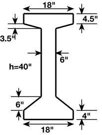
 depth of bearing plate
 depth of member
For  ,
,
(2) 
 tension force in the ‘bursting’ zone
The resultant tensile force in the ‘spalling’ zone above the tendon is about  (empirical)
e.x.
Each tendon consists of  diameter low-relaxation strands with
  , stressed to
  ,
, mild reinforcement
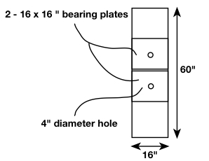
Check the bearing stresses under the anchor plates:

Net bearing area of each plate:

 , which is about
We can treat the two bearing plates as a single bearing plate with bearing area  , and subjected to a tendon force of
(3) 
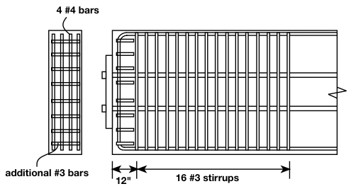
In order to keep the stress in the reinforcement below  , the minimum total stirrup area, required in the ‘bursting’ zone, is:

How many #3 stirrups is this?
 stirrups
We can use 16 stirrups, spaced at 3.5”, with the first stirrup at 12” from the end face.
In order to control ‘spalling’, we need to resist a tensile force of  .
.

How many #4 bars is this?
 (note that these could be straight bars as opposed to U-shaped stirrups)
We can conservatively use 4 bars.
Additional #3 bars will be used at the end face for confinement.
Importance of proper stirrup spacing in anchorage zones:
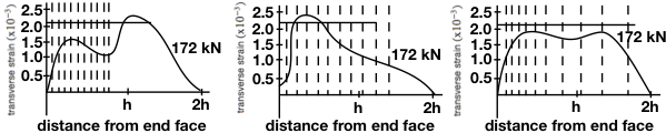
We want to avoid the situation on the far left. The far right is ideal. The middle is acceptable, and is the easiest to implement.
Linear Elastic Stress design:
e.x.
Design the end anchorage reinforcement for the post-tensioned beam shown below, which spans 


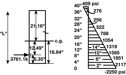
Distance of tendon (or centroid of tendons) from the bottom fiber:

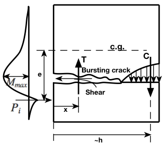
Within the anchorage zone, the span to depth ratio is small enough, that we basically have something analogous to a beam of length  shown below. Recall from statics, that the internal bending moment can be found from the ‘cutting’ method. This moment can be found from either the left FBD or the right FBD. In our case, our ‘beam’ can be thought of as resting flat on the ground and our FBD is to choose from are either top or bottom rather than left or right. We will choose bottom.
The concrete internal moment at the plane 4” from the bottom fibers:
(4) 
The concrete internal moment at the plane 8” from the bottom fibers:
(5) 
We’re using width  since this is the average width between
  from the bottom fiber and
  from the bottom fiber.
The prestressing force moment at the plane from the bottom fibers is
(6) 
The net moment is then 
We can repeat this procedure throughout the height of the beam to obtain the maximum positive and negative moments.
Moment plane distance 'd' from the bottom  |
Section width |
Moment from tendon about the horizontal plane of interest  |
Moment from concrete about the horizontal plane of interest  |
Net moment |
|---|---|---|---|---|
0 |
18 | 0 | 0 | 0 |
4 |
18 | 0 | 0.30 | 0.30 |
6.35 |
13.3 | 0 | 0.75 | 0.75 |
8 |
10 | -0.62 | 1.12 | 0.50 |
12 |
6 | -2.14 | 2.25 | 0.12 |
16 |
6 | -3.63 | 3.54 | -0.09 |
20 |
6 | -5.13 | 4.94 | -0.19 |
24 |
6 | -6.64 | 6.44 | -0.20 |
28 |
6 | -8.14 | 7.99 | -0.15 |
32 |
6 | -9.65 | 9.61 | -0.04 |
36 |
18 | -11.15 | 11.13 | -0.02 |
40 |
18 | -12.66 | 12.66 | 0 |
We can take  to be
to be  here and conservatively ignore any resistance to tension from the concrete itself. It is important to note that this is very conservative and can also give the misleading impression that wider anchorage zones actually adversely effect anchor zone reinforcement, which we know not to be true.
Bursting zone:
(7) 
Take  (code allows
  )
)
(8) 
Spalling zone:
(9) 
where  is the largest negative moment
(10) 
Stirrups can then be proportioned as appropriate
Strut-and-Tie design:
e.x.
Each tendon consists of  diameter low-relaxation strands, stressed to
  , where

Post-tensioned anchorage zones must be designed to withstand the ultimate tensile force of the tendons:
For each tendon:
 (4 strands per tendon)
Compressive stresses:
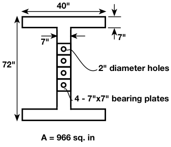
Net bearing area of each plate:
(11) 
Bearing stress 
where  is the force from one tendon
Permissible nodal stress limit:
(12) 
Outside of the immediate bearing region, the compressive stress can be idealized as uniform:
(13) 
This results in a compressive force of  , in each flange, and
  in the web
The total bearing force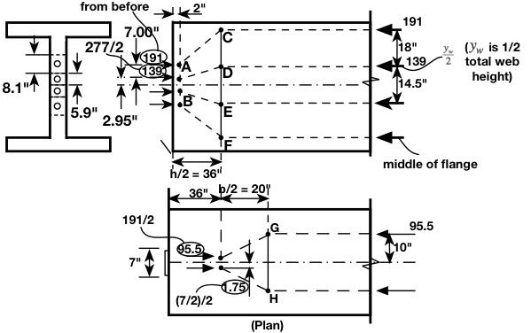
 can be distributed, using the strut-and-tie model shown:
The total bearing plate height is in fact  , but the holes are not necessarily drilled in the center of each plate.
Force in kips
Member
CD = EF
DE
GH
127.6
173.9
39.4
If #4 stirrups are used  , each stirrup has a factored tensile resistance of
since  governs,
  stirrups
 Use 9 – #4 stirrups, space at
We need stirrups at the end face to control spalling cracks
Recall that can be taken as the spalling force: 
The 21.6 kip capacity of a #4 stirrup exceeds this 
We can use straight #4 bars placed transversely in each flange to resist the force 
 stirrups (note the bar force was not doubled this time, since these are NOT stirrups)
Use 4- #4 bars spaced at  in each flange