Strain is a measure of deformation that has an intuitive physical meaning for engineers. Specifically, axial strain, for example, is a measure of the deformation of a structure (or element within a structure) with respect to the structure’s length. Thus, strain is a ratio of lengths and is a unit-less quantity. While strain can come in the form of extension, shortening, or shear strain, it is sometimes overlooked that strain also has direction. This change in direction, under, for example, rigid body rotation, creates some interesting complications in the finite element world.
In the finite element world and, accordingly, in solid mechanics (“solid” or “continuum” elements), we essentially calculate the strain at every point within a structure. Even for very simple geometries subjected to symmetric loads, some of the points (elements) within a structure will undergo rigid body rotations. Such rigid body motions present a complication: the elements comprising the structure need to maintain a consistent frame of reference. The need for a consistent frame of reference is even more apparent when one considers impact type behavior that involves multiple bodies.
If the reader is familiar with the idea of “geometric nonlinearity,” then following analogy may be useful. Consider the manner in which structural engineers perform the preliminary design of the beams and columns of tall buildings. They often design for maximum flexibility, using efficient analytical methods. Where gravity and lateral loads act simultaneously on a building, these engineers know that the force demands in the structure from the gravity loads should be calculated after the force demands from the lateral loads are determined. The lateral loads cause the building to sway, and the presence of rigid body rotation of the columns is important to consider prior to calculating the force demands from the gravity loads. Similarly, in FEA, there is a certain order to the treatment of rigid body rotation in the FEA algorithms, which we will see when we get to the chapter on “Rate-Form Constitutive Expressions.” It is important to recognize this now, however, because we will begin discussion of strain and many different measures of strain will be presented. Different strain measures are used in FEA, depending on the order in which rigid body rotations are considered.
Since the analytical methodology for building design was mentioned, now is a good time to remind the reader that the kinds of FEA analysis that this text considers are fundamentally different from analytical methods of design and analysis. ABAQUS/Explicit and LS-DYNA are examples of the kinds of FEA software considered in this text. Here, geometric nonlinearity is not an issue. Rather, we are free to model structures of complex geometries subjected to any loading conditions we wish. In addition, the behavior of “solid” elements are governed by continuum-type mechanics, and so “moments” will not be considered. To really develop the framework used by FEA codes, though, we need to consider stress, as well as constitutive expressions relating stress and strain, including “hyperelasticity.” This chapter only provides an overview of the various strain tensors that will be used later on in this text.
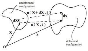
Consider a body that undergoes deformation as well as rigid body rotations (see Figure). In particular, we’ll consider a vector that is initially ![]() , and well will track this vector as it becomes
, and well will track this vector as it becomes ![]() .
.

(1) ![]()
In eq. 1, ![]() is a second-order tensor known as the “deformation gradient”
is a second-order tensor known as the “deformation gradient”
We can see from the above figure:
![]()
![]()
where ![]()
In index notation, ![]()
where ![]() , which comes from a Taylor expansion and neglecting higher order terms
, which comes from a Taylor expansion and neglecting higher order terms
i.e. ![]()
So, ![]() or
or ![]()
note the “Nabla” or “gradient” symbol ![]() that is a commonly used operator. Also, note that
that is a commonly used operator. Also, note that ![]() is the transpose of
is the transpose of ![]() .
.
So, ![]()
