Rules of Thumb:
Preliminary choice of section depth: 
Note: the method outlined in the previous section on ‘Required Section Moduli’ is more precise, albeit more cumbersome. A rule-of-thumb is typically used in practice.
Preliminary choice of  is based on ultimate strength:
Note: the working stress method outlined previously did not take into account ultimate strength.
Ultimate strength analysis, as well as deflection analysis, will be included in the examples to follow.
Double-Tee, pretensioned, floor member (simply supported)

 , low-relaxation
Concrete strength at transfer, 


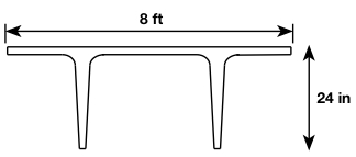
A  beam would have a span-to-depth ratio of about
  . We can try the following section:
note: The previous procedure used a much more complicated approach for choosing a section size. While that approach may be optimal for a simply supported beam or an I-shape (where moment reversal is not an issue due to the symmetry of the section shape), the previous approach is generally viewed as being overly complicated. Additionally, deflections were certainly not considered in the previous procedure, whereas this rule-of-thumb is based on practical experience, with consideration of deflections.


Preliminary design (based on final stage, midspan stresses):
(1) 
(2) ![\begin{equation*} M_{u} = [1.4(.418 + .120) + 1.7(.400)]\frac{46^2}{8} = 379ft*kips \end{equation*}](https://utsv.net/wp-content/ql-cache/quicklatex.com-f9c078bbddc9f3f19b41d9f5dfac65c3_l3.png "Rendered by QuickLaTeX.com")
Note: load factors may vary depending on the code that is used
 (from the table in the previous section)
Note: this is not as accurate as our previous example, since  is just an approximation


Also, we can solve for  :
: 

(3) 
If we were looking at the intermediate stage, as we did for the previous example, then we would be using the inequality [ expression].
In our earlier example, we essentially found and  from optimizing stresses at the intermediate stage (larger and/or would cause simultaneous crushing and cracking at the intermediate stage).
Essentially, here, we’ve found and  , by optimizing the bottom stress at the final stage (a smaller and/or would cause tensile cracking at the final stage). Crushing is not considered. However, for a T-beam, it is probably satisfactory to neglect crushing under service loads, since it is so unlikely due to the relatively large compression flange.
For low-relaxation strands, stressed to  and
and 

In addition, rule-of-thumb:


Use six  strands for
Check of intermediate stage, midspan:


 (the 187ksi accounts for immediate losses, such as elastic shortening; some codes may use 189ksi)

Any larger, and the top face would crack in tension at the intermediate stage (crushing is not considered).
Our  eccentricity, found earlier from
  , is less than this value. In fact, we can increase this value to
  , which is the full depth of the beam minus
  cover.
Note: We will assume that the tendons are harped, with an “” of about  at the support.
Note: The previous example had calculated and based on the initial condition, and then checked the final condition. Here, we did the opposite: we calculated and based on the final condition, and then checked the initial condition. This is not the only difference between the two methods. Firstly, for the first method, if the required section modulii equations were used, then the final condition would not actually need to be checked. The fact that the stress capacities would exceed demands at the final condition would have been implied. Secondly, checks to ensure that stress demands fall below both the crushing and the cracking limits, are also implied, for the first method. For the latter method, only cracking has been considered.
So far, we’ve only looked at midspan. At other locations,  and
and  differ (both will be smaller in this case), so these other locations need to be checked.
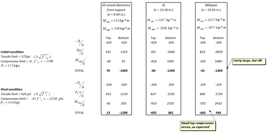
We’ve also neglected crushing so far, which is probably not a satisfactory assumption for the transfer stage, where the compression will be in the web of the T-beam. Thus, we will check the stresses (both tensile and compressive) at midspan as well, which includes compression.
The following table shows the concrete stresses, in units of psi:
Ultimate strength check:
For pretensioned members or post-tensioned with bonded tendons (empirically derived):
(4) ![\begin{equation*} f_{ps} = f_{pu}(1-\frac{\gamma_p}{\beta_1}[\rho_p\frac{f_{pi}}{f'_c} + \frac{d}{d_p}(\omega -\omega')])\end{equation*}](https://utsv.net/wp-content/ql-cache/quicklatex.com-c9e82a37a8ab1df214f5aa692ab482fb_l3.png "Rendered by QuickLaTeX.com")
Recall  from the following equation:


 for stress-relieved strands
 for low-relaxation strands

If mild reinforcement is present:
 and
and  are the distances from the extreme compression fiber to the centroid of the mild reinforcement and to the centroid of the prestressing steel, respectively
 and
and 
Additional constraints:
![[\rho_p \frac{f_{pu}}{f'_c} + \frac{d}{d_p}(\omega - \omega')] \leq 0.17](https://utsv.net/wp-content/ql-cache/quicklatex.com-16b34882a3309adc3723949d93aaf4fa_l3.png "Rendered by QuickLaTeX.com") , if compression reinforcement is accounted for.
, if compression reinforcement is accounted for.
If  is greater than
  , then
  .
.
So, back to our example problem, assuming no mild reinforcing:
(5) 
Note: additional check:
(6) 
Now we will find the ultimate moment capacity exactly as done in ordinary reinforced concrete:
(7) 
(8) 
This is greater than 
There is an additional ‘ductility’ check which relates  to
to  :
:
We need to calculate , which is not a small value and can be calculated as follows:
We can take a realistic concrete tensile strength to be 
Note from the above table of working stress demands for our beam, that the tensile stress at the bottom fiber, at midspan, under final conditions, is  .
.
Hence, to cause cracking, an additional tensile stress of  , is needed.
Hence, an additional moment of  would be needed, on top of the moment of
  from service load. This results in a total moment of
  to crack the beam. Now we can check that our ultimate moment capacity is significantly greater than this value, in an attempt to ensure under-reinforced behavior.
(9) 
Deflections:
Multipliers for estimating long-term cambers and deflections
| Composite | Non-composite | |
|---|---|---|
At transfer: |
||
Deflection from member self-weight |
1.85 | 1.85 |
Camber from prestressing |
1.80 | 1.80 |
At final stage: |
||
Deflection from member self-weight |
2.70 | 2.40 |
Camber from prestressing |
2.45 | 2.20 |
Deflection from superimposed DL and 30% LL |
3.00 | 3.00 |
a) Immediate deflection due to LL:

 , where
  (Live Load)
This is less than 
b) Check deflections likely to damage partitions
We will assume non-composite construction for this example.
To calculate the deflection that will affect partitions, we must first estimate the deflection of the member at the time that the partitions are attached:

 , where
  (self weight)
Note:
For a single harping point, 
For a draped tendon, 
We will assume a single harping point here:
(10) 
Now, we need to account for a small amount of creep during erection time, so we use the multipliers in the above table:
 (upward)
This is the deflection of the member at the time that the partitions are attached.
 , where
The long term deflection =
def due to self-weight + def due to PT + def due to  , with each of these three terms being multiplied by appropriate factors from the above table to account for long term creep and relaxation:
 (upward)
Note: we could’ve used rather than , but these values are already conservative enough, since we’re using a very low  value based on
  .
.
So, the long-term deflection that occurs after the attachment of partitions, is:
 (downward)
At any point in time, there could be the addition of the rest of the live load, causing an additional immediate deflection of:
 , where
  was calculated in part ‘a’
Thus, the total deflection that would cause the partitions to potentially crack, is:

(Strict limit for deflection sensitive parts)

Rather than using the multipliers in the table, creep coefficients could have been used, as was done in the ‘deflections’ section, for ordinary reinforced concrete.